Noise, Dynamic Range and Bit Depth in Digital SLRs
by Emil Martinec ©2008
last update: February 11, 2008
restored and reposted with permission by Bill Claff: August 15, 2015
Aspects of Noise Reduction in Raw Data
Noise reduction of raw data: Noise reduction applied directly to raw data before raw conversion can confer substantial benefits. There are two broad classes of noise reduction:
Correlated double sampling (sometimes referred to as "on-chip NR"): In preparation for a new exposure, the electrons liberated by photon capture from the previous exposure must be emptied from the sensels; each sensel must be reset to a state of zero exposure. If this process is not completely effective, there may be residual electrons present in the sensel prior to the next exposure, and these electrons will throw off the count of photons from this new exposure. The fluctuations in the number of electrons present after zeroing out the sensel constitutes the reset noise.
An advantage of CMOS sensors is their ability to read the state of the pixels non-destructively -- the state of the sensor (its count of electrons) can be read off without affecting that state. This feature can be used to eliminate the reset noise as follows. After the sensor is reset from the previous exposure, the state of the sensor is read, giving a count of the residual electrons of the reset noise while leaving those electrons in place; then, after the exposure, the sensor is read again, the result being the residual electrons plus those added via photon capture during the exposure. Taking the difference of the two readings gives the photo-electron count of the exposure while subtracting off the reset noise. This before-and-after reading of the sensels is known as correlated double sampling (CDS). On CCD sensors, the electrons in a CCD sensel must be extracted from the sensel and transferred to the edge of the sensor in order to do the readout; CDS can be performed in this per-column readout circuitry rather than separately within each sensel. The double read adds time to the readout when done serially at the edge of the sensor rather than in parallel at each sensel. CDS is a feature of most current CMOS DSLR sensors, see for instance the product literature by Canon and Sony.
Pattern read noise subtraction: Some forms of noise are unchanging from image to image; an example is the fixed pattern noise component of read noise, discussed on page 1. Since it is unchanging from image to image, what one needs is to develop a master pattern noise template, an image file that contains only the pattern noise; taking the difference of a raw image and the pattern noise template before raw conversion removes the pattern noise.
But how does one construct a template containing only the pattern noise and nothing else? After all, won't any raw file include not only the pattern noise but also every other kind of noise we've been discussing? The point is that other forms of read noise vary from image to image. By averaging over many blackframes, these variable contributions to noise average to zero, leaving only the pattern noise which is the same for each blackframe.
In effect, one is using the pattern noise as a "signal" and using same math as in the pixel-binning discussion on page 3. Here, instead of binning together neighboring pixel raw values on the same image, one bins together the raw values of the same pixel on different blackframe read noise images. Since the fixed pattern noise is unchanging from image to image, its contribution to the total increases in direct proportion to the number of blackframe images added together. On the other hand, the variable noises fluctuate up and down and combine in quadrature because they are varying independently from image to image. The result is that, adding together M images, the pattern noise is increased by a factor M, while the variable noises go up by only sqrt[M]; dividing by M to take the average, the pattern noise has its original strength in the combined image while the fluctuating noise component goes down by a factor sqrt[M].
Note that the construction of a pattern read noise template is substantially more difficult for cameras (e.g. Nikon) that do not include a bias offset before writing out the raw data. All negative noise fluctuations get truncated to zero, and so the random fluctuations do not avearge out to zero when a stack of blackframe images is combined to make the template. For cameras with such a bias (e.g. Canon), the output of the stacking process is directly the template.
Having the pattern noise template in hand (a separate one should be constructed for each ISO, since read noise changes with ISO), it can be subtracted from any given image and the fixed pattern component of read noise will be removed. The variable component R of read noise will increase slightly (by an amount R/M) as the residual variable read noise of the template and the variable read noise of the image combine in quadrature. The more images are stacked together to make the template, the smaller this effect is; in practice ten or so blackframes are sufficient to make a good template (I used 16 to make the template used on page 1).
PRNU compensation (flat field correction): A similar procedure to that just discussed can in principle compensate for pixel response non-uniformity, though in practice it's probably not worth the trouble. PRNU is like fixed-pattern noise in that it is a fixed property of the sensor that doesn't change from image to image; it is different in that the strength of PRNU varies with exposure. Because PRNU is the most important source of noise at low ISO and high exposure, it is best isolated by taking images at the lowest ISO and about 1/2 to 1 stop down from sensor saturation. The biggest competitor to PRNU in this regime is photon shot noise. Again this is random while PRNU is fixed, and so photon shot noise is eliminated from a PRNU template by averaging together a number M of so-called flat fields. A flat field exposure is an image of a uniformly illuminated featureless surface. Taking the average of M such images, again the varying shot noise goes down relative to the fixed PRNU by a factor sqrt[M].
It is important that the illumination is as uniform as possible (in particular, no gradients) over the image or the correction will introduce tonal shifts across the image; it is also helpful to have all three color channels toward the right edge of the histogram so that PRNU exceeds shot noise substantially in all color channels. Finally, the flat field images will also incorporate the vignetting of whatever lens is used to make them; this effect can be mitigated by stopping down the lens a couple of stops to make the flat field. Dust spots are another contaminant, so the sensor should be as clean as possible.
PRNU is due to variation in response to light from pixel to pixel;
if you like, each pixel has a slightly different gain. The flat field
image is a map of the gain variation. Thus, if we take an image
and divide its pixel raw values by the corresponding pixel raw values
of the flat field (something that can for instance be done in
the astrophotography software
IRIS)
the variation in gain will cancel out between the two,
and PRNU will be removed. On average, this procedure will also end up dividing
pixel values by the average illumination level of the flat field image, and
so to restore original illumination level to the corrected image one
should multiply by the average illumination level L of the flat field image.
Also, for cameras with a bias offset of black
(e.g. 1024 on 14-bit Canon raw files),
the offset should be removed
from both the image and the flat field before doing the division (this will be
done automatically if we subtract a pattern read noise template from both images
since the template will also be offset and the bias will cancel out).
In equations, the manipulation to be done to remove PRNU is
corrected image = L*(image - offset)/(flatfield - offset)
where if desired one can substitute the pattern read noise template for
the constant offset in order to remove pattern noise at the same time.
Dark frame subtraction: In situations where there is substantial thermal noise, typically long exposures, it may become helpful to attempt to subtract off the contribution of thermal noise from the image. The procedure here is similar to those above -- take several dark frame images at the same exposure time and operating temperature as the image file (since the amount of thermal noise grows with both exposure time and operating temperature), and average them together. The resulting thermal noise template will consist largely of thermal noise (and also fixed-pattern read noise), and when subtracted from the image, thermal noise effects (especially amplifier glow in long exposures) will be mitigated.
This is exactly the procedure that is carried out by the camera when long exposure noise reduction (LENR) is enabled -- after the exposure, the camera holds the raw image in a memory buffer while a second dark frame exposure is taken for the same length of time with the shutter closed. The resulting dark frame image is subtracted from the stored image and then written out to the storage card.
It can be rather inconvenient to have to wait while the camera
takes essentially the same dark frame image for each exposure;
essentially half one's time is spent waiting for the camera
to complete the dark frames. It is more efficient to take a
set of dark frames after the fact, for each shutter speed
used in the the session, providing master dark frames that can
be used for many images. Moreover, in-camera LENR uses only
a single dark frame for the subtraction; while this may
help remove thermal noise from the image, read noise adds
in quadrature between the image and the dark frame, and thus
increases by a factor sqrt[2]~1.4.
What would be extremely useful is a software application that would allow one to reinsert the noise-processed but unconverted image data back into a raw format that standard converters could then process. IRIS and dcraw can unpack a raw file into a data format such as FITS, PGM, or TIFF; and IRIS or similar applications can perform the needed noise reduction algorithms on the extracted raw data. The missing link in the processing chain is a simple application that would take as inputs the processed raw image as well as the original raw file (whose importance lies in the image metadata it contains, which are largely or entirely stripped by the applications that are capable of doing the NR), then insert the processed image in place of the unprocessed image, and write the output to a standard raw format (for instance, a raw DNG file). Then any raw converter that understands the standard raw format can process the result, and the user can employ their standard workflow from then on.
In-camera filtering of raw data: All the above noise reduction methods involve manipulations at the level of individual pixels; never is a pixel value compared to or mixed with neighboring pixel values in attempting to eliminate noise. These methods are thus quite different from what is conventionally called noise reduction in image processing. Noise reduction programs such as Noise Ninja, Neat Image, as well as noise filters such as the median filter in Photoshop and their kind, act by comparing and averaging nearby pixels in order to reduce the appearance of noise. This form of noise filtering is sometimes also applied to raw data, typically for long exposures or high ISO images where noise can be problematic.
An example of this sort of filtering being applied to raw data before it is written occurs with high ISO images on the Sony A700, as reported in reviews of the camera at DPReview and Imaging-Resource. How does one detect such filtering? One way is to examine a uniform tonality patch of an image, and ask how much noise is present at different spatial scales.
Noise is the random jumping around of pixel values by an amount typically between -N and +N, where N is the magnitude of the noise; for the most part that random jumping about occurs independently for each pixel. As was mentioned in the discussion of photon shot noise, the spatial dependence of shot noise (and the spatial dependence of the largest component of read noise) is that of white noise -- equal magnitude fluctuations at all spatial frequencies. What this means is that the jumps between a pixel and its neighbor are just as big as the jumps between the pixel and its next-nearest neighbor, and the pixel three steps away, and so on. An example of noise that is not white is banding noise; for instance, in horizontal banding noise if a pixel is a little brighter than the average, chances are that the pixels up to a sizeable distance away in the same row of the sensor are all a little brighter than the average, while the nearby pixels in the vertical direction have unrelated values.
Noise reduction filters act locally -- they compare nearby pixels and try to reduce the magnitude of the random jumping about of their values in a small neighborhood. After filtering, nearby pixel values are more similar, while a difference of a pixel's value from one further away hasn't been filtered, and are much the same as before. The result is that noise filtering typically removes the fluctuations in pixel values on small scales, leaving them largely intact at large scales. This effect can be made quantitative by examining the Fourier transform of the image.
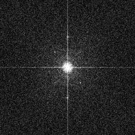
The Fourier transform (FT) is a representation of the image data by spatial scale rather by spatial position on the sensor (which is of course the way the sensor records it). In a Fourier transform plot, the effect of noise reduction will be a decrease in the noise amplitude on the smallest scales. An example is shown in Figure 22
Fig. 22 -- The Fourier transform of an image of a blank wall. The uniform speckling away from the center indicates that the noise spectrum at high frequency is flat all the way out to the pixel level, an indication of minimal correlation in the fluctuations of neighboring pixels. Mouse over to see the effect of a mild median filter; the darkening toward the edges is the sign of the dampening of the noise spectrum at high spatial frequency, due to the averaging over neighboring pixels (smearing due to noise reduction, in plain terms).
Using this 14-bit NEF file of a brightly exposed uniform wall at ISO 200, a Fourier transform was applied to the green channel data both before and after applying a mild adaptive median noise filter (the command "af3 .2" in IRIS). The FT plot places high spatial frequencies (small spatial scales, or effects at the pixel level) at the edges of the plot; effects at small spatial frequency (large spatial scales, or effects uniform across the entire image) appear at the center of the plot. In the original image, the FT plot is uniform away from the center, indicating a nearly white noise spectrum (the bright spot in the center is due to a mild speckling of the wall brightness at large spatial scales; the vertical and horizontal lines passing through the center of the plot are indications of one-dimensional structure -- banding noise). The effect of a mild median may filter may be seen by mousing over the image; the darkening toward the edges of the FT plot of the noise-filtered image is an indication that the noise has been reduced at fine spatial scales, but not altered on larger scales.
High ISO noise reduction manifests itself similarly in the FT of uniform patches of Sony A700 raw data. The Fourier transform of a uniform patch of wall in this ISO 6400 high NR image (warning: 18.5MB raw file) shows the telltale signs of noise filtering, similar to the median filter example above:
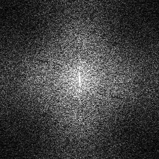
Fig. 23 --
Noise reduction filtering is apparent in the Fourier transform of
a high ISO image raw data from the Sony A700.
The filtering is most apparent in the red and blue channels
(the red channel is shown here).
Another example of noise filtering arises with long exposures in Nikon DSLR's. Figure 24 shows a sequence of Fourier transforms of successively longer exposures from the Nikon D300 (plots courtesy of Bill Claff).
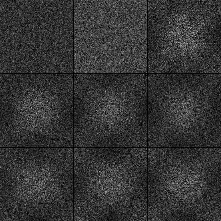
Fig. 24 -- Noise reduction filtering is apparent in the Fourier transform of long blackframe exposures on the Nikon D300.
The shutter times were 1/15, 1/8, 1/4 1/2, 1, 2, 4, 8, and 15 seconds from left to right, and top to bottom. One can clearly see noise reduction has been applied at 1/4s and longer exposures. The noise reduction will of course reduce the width of the noise histogram; a plot of the the amount of noise as a function of exposure time indeed shows the onset of noise reduction above 1/4 second exposures on the D300:
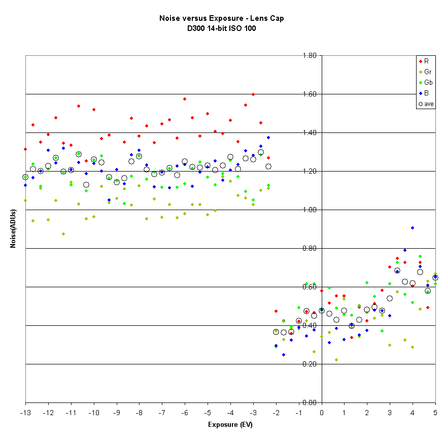
Fig. 25 -- Noise reduction filtering is apparent in the width of the noise histogram on long blackframe exposures on the Nikon D300. Data courtesy of Bill Claff.
The problem with these alterations of raw data is that the user cannot turn them off! Image data is irretrievably adulterated by the noise reduction process.