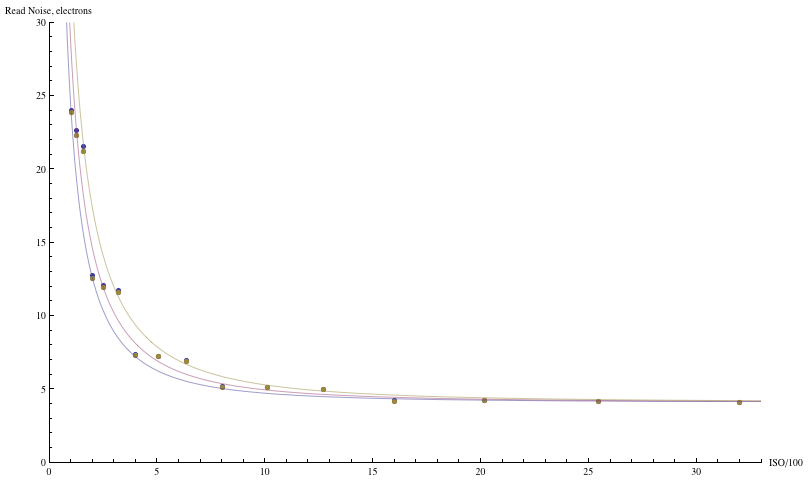
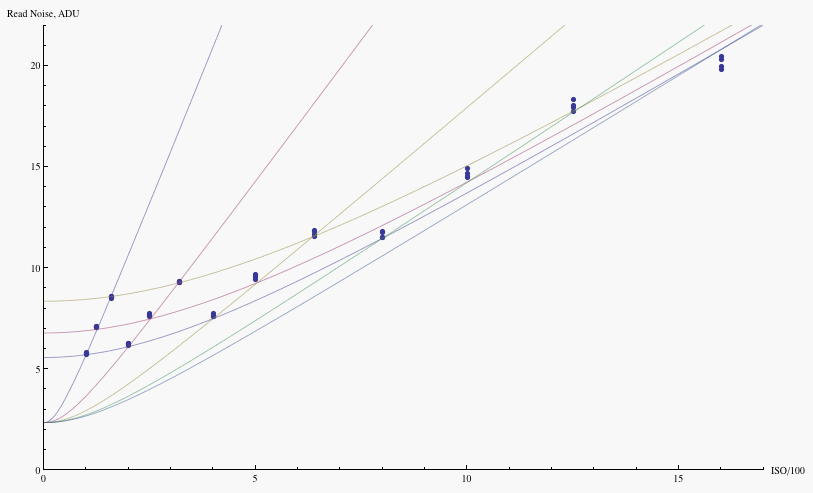
Fig. 15a - Read noise vs. ISO for the Canon 1D3 in photoelectron
equivalents.
Points are data,
courtesy of Peter Ruevski; the curves are a fit to the read noise model.
Noise, Dynamic Range and Bit Depth in Digital SLRs
by Emil Martinec ©2008
last update: August 6, 2008
restored and reposted with permission by Bill Claff: August 15, 2015
Sensor Dynamic Range vs. Camera Dynamic Range
The read noise vs. ISO graphs on
on page 2
exhibit noise (as measured in raw levels) increasing with ISO.
The observed values were accurately fit by the model presented
on page 2;
in its basic form, the model gives the read noise R as
R2 = (G R0)2 + R12
in terms of the noise R0 coming
from circuit components upstream of the ISO amplifier, whose ISO gain
is set to G; and R1 is the noise arising from circuit components
downstream of the ISO amplifier.
Note that the effect of increasing the ISO gain emphasizes the contribution
of the upstream noise component, to the point that at high ISO
the read noise is almost entirely due to upstream noises, with a
negligible contribution from downstream noises.
The noise measured in ADU is sometimes called output-referred noise,
the noise in the output raw data after all the amplification etc that goes on in
the signal processing chain. It is sometimes useful to express the noise
in terms of its input equivalent, in photoelectrons at the photosite, in order
to compare it to the photon noise or the signal, both of which are measured
in photoelectrons. This is accomplished by multiplying
by the gain g=U/G , the conversion factor between electrons and ADU; here,
U is a constant (the so-called universal gain) and G is the ISO setting.
When this is done, the opposite trend is observed --
read noise goes down with ISO in electron equivalents:
(R in electrons)2=[ g * (R in ADU) ]2 = U2 (R02 + R12/G2)
Fig. 15a - Read noise vs. ISO for the Canon 1D3 in photoelectron
equivalents.
Points are data,
courtesy of Peter Ruevski; the curves are a fit to the read noise model.
With this way of plotting the data, it becomes clear that the downstream contributions to read noise are a big limiting factor in S/N performance and dynamic range at low ISO. If the read noise at low ISO were only due to the upstream noise sources, and received no contribution from downstream sources, the read noise curves of Figure 15a would be essentially flat; the noise floor at low ISO would be dramatically lower, and low ISO dynamic range would improve by a factor of over four (two stops). The range over which S/N is limited by photon statistics rather than sytem read noise, would expand another 4-5 stops over the current range.
Consider again the S/N vs exposure curves of Figure 12 on page 2. Those were plotted using the signal level in raw levels, but what a raw level means changes as the ISO is varied. Instead normalizing the curves to the same absolute exposure in EV, exhibits the dynamic range windowing as function of ISO:
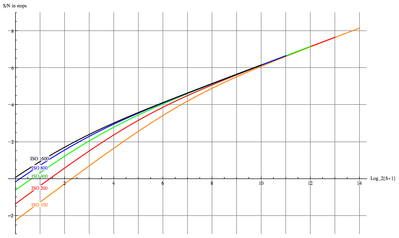
Fig. 12a - Signal-to-noise ratio of the Canon 1D3 for various ISO, as a function of normalized exposure value.
When the ISO is doubled, one more stop or EV of input is pushed past the saturation point of the ADC and is lost; thus each subsequent one stop increase of ISO removes one stop of highlight exposure. At the low end is the noise "floor", really the point at which one chooses to quit using the sensor data because the signal/noise ratio becomes too poor. This floor varies with ISO, and thus how much room on the noise floor is available depends on ISO. From Figure 15a we see that, in normalized exposure terms, the floor is lowered with increasing ISO. The sensor doesn't know what ISO gain is going to be used, it just records whatever photons arrive, leaving it to circuitry off the sensor to amplify the signal and digitize it. This means that the sensor sees the *entire* range of the figure -- the upper bound or "envelope" of all the different curves. The sensor has about 14 stops of DR, but the limitations of the rest of the circuits allow the final raw data to see less than twelve stops of DR, and the user is forced to choose a "window" of EV within that 14 stop range by selecting the ISO gain. The result is that, in terms of absolute exposure, one has a "window" between noise floor (the minimum S/N ratio deemed acceptable) and saturation, which is the DR for that ISO. Each subsequent stop of ISO amplification lops off one stop from the upper end, while the room on the lower end improves because read noise drops in absolute exposure terms with increasing ISO, until it saturates about ISO 1600.
Note that the expansion on the bottom end yields less and less -- going from ISO 800 to 1600 doesn't make much difference in shadow S/N, but one loses an entire stop of raw headroom. Above ISO 1600 there is no expansion of the shadow range whatsoever, just more and more lost from the top end. This is why it makes no sense to use absurdly high ISO's like 6400 in raw capture -- one loses a great deal of highlight headroom without getting anything back at the shadow end; it's better to underexpose by a stop or two at ISO 1600 if one needs the shutter speed, than to use a higher ISO.
This windowing of DR is occurring because the camera doesn't deliver the full DR that the sensor is capable of at base ISO; rather it is limited by the rest of the electronics -- the ISO amplifier and ADC. The sensor has a DR of about 14 stops, while the amp/ADC have a bit less than 12 stops DR. There are about two stops of extra dynamic range to be had in DSLR's that is currently being thrown away by limitations of components other than the sensor. This is true of both Canons' and Nikons' CMOS DSLR's.
Dynamic range at ISO 100 is limited at the bottom end of the range by the noise of the electronics after the sensor output; the dynamic range at ISO 1600 is much less limited by the read noise, and is instead limited by the saturation level at the upper end of the range, since every doubling of ISO clips another stop of highlight data. So currently, one must choose which parts of the sensor's DR to throw away since not all of the data on the sensor can fit into the DR of the downstream electronics. One has to either throw away data at the low end through noise in the downstream circuitry, or one has to throw away data at the high end due to clipping.
The large contribution of these downstream noises affects the calculus of whether smaller pixels can perform as well as larger pixels in terms of image level signal-to-noise ratio. It was observed that a current 2 micron pixel digicam, the Panasonic FZ50, did about as well as the best large pixel DSLR's in terms of both read noise and photon collecting efficiency. But the read noise for the large pixel DSLR at low ISO is due to system components that have nothing to do with the photosite read noise performance, while the read noise for the digicam are attributable predominantly to the digicam photosite. So in comparing large pixels to small pixels, if the issue is how well are the pixels performing, the comparison should be made at high ISO where the measured read noises of each are due to the contributions from the photosite. By this measure, the big pixels always win when data from current cameras are compared; not because they collect less light -- as was seen on page 3, the light collection efficiencies are comparable -- but because the read noise of the larger pixels is smaller on a per area basis.
If the DR of the downstream components were not a limiting factor, then when recording at ISO 100, the highlights would be available, but the read noise would be predominantly due to the sensor itself and thus have the same value in electrons as the read noise at ISO 1600. For the 1D3, ISO 100 read noise, limited by the downstream components, is about 24 electrons; ISO 1600 read noise, coming primarily from the sensor, is only four electrons. Because of this factor of six difference in read noise, the full sensor dynamic range is over two stops higher (about 14.0) than the camera delivers (about 11.7) due to those downstream components.
This hidden extra dynamic range is what Roger Clark calls "sensor dynamic range" -- the saturation capacity of the photosite in electrons, divided by the high ISO read noise in electrons. This sensor dynamic range is distinct from the delivered camera dynamic range at any given ISO, which is the raw saturation level divided by the read noise, both as measured at that ISO; it is higher than the delivered dynamic range by the difference between the system read noise and the sensor contribution to it (or rather their ratio, in stops).
Even so, this benefit of large photosites at low ISO is largely useless until camera manufacturers find a way of unlocking the potential of their big-pixel sensors by getting the downstream electronic noises out of the way. Could it be possible to recover the full DR seen by the sensor?
It might well be possible. What one would like is to somehow be able to use ISO 100 to keep all the highlights, while at the same time using ISO 1600 to recover all the shadows. But how can one have two ISO settings at once? By having two separate amplifiers fed from the same sensor data, running in parallel. Suppose that the sensor signal is sent to two separate processing paths, each path an amplifier and an ADC, with one amplifier set to ISO 100 and the other to ISO 1600. The ISO 100 path keeps all the highlights but has noisy shadows; the ISO 1600 path loses the top four stops of highlights but has much better shadows. Quantizing each, one can then combine the image data in a manner similar to HDR processing to yield an image with all 14 stops that the sensor is capable of recording. What would the result look like? Well of course, no such camera is currently made, but one can get an idea of the possibilities by shooting two successive images, one at ISO 100 and another at ISO 1600, and combining the two, as demonstrated in the following simulation:
Fig. A1 - HDR blend of ISO 100 and ISO 1600 images.
Fig. A2 - HDR blend of ISO 100 and ISO 1600 images. Pixels outside the blending window are set to black.
Fig. A3 - Detail of HDR blend of ISO 100 and ISO 1600 images.
Fig. A4 - Comparable region to Figure A3, ISO 100 image only.
Fig. A5 - Shadow region, ISO 100 image only.
Fig. A6 - Shadow region, HDR blend of ISO 100 and ISO 1600 images.
As an aside, now that one is recording all the data that the sensor has to give, there is no reason to have a variable ISO gain, just the fixed 100/1600 parallel channels (or whatever two fixed amplifications optimize the data extraction). The ISO setting can be put into metadata like white balance is, a suggestion from the camera's metering to the raw converter as to what exposure compensation to apply in order to develop the image. As discussed on page 3, so long as noise sufficiently exceeds quantization step, there is no difference between amplification in hardware during the capture process, and amplification after the fact during raw conversion.